Sunday, May 5, 2013

Final Post: The Completed LED Lamp

After many weeks of working and many hours in the engineering lab, our LED lamp is finished! It is ready for exhibition in the Science Center next Wednesday.

Description of the LED Lamp:

The LED Lamp is a lamp that gives off light from three LED-encrusted paper spheres which hang from a stand. The lights respond to the light cast upon them by brightening or moving.

Physical Construction:

The main structure of the lamp is a wooden stand with a triangular central stem and a circular platform. The stand was laser-cut and is held together with interlocking notches (the notches connecting the platform are superglued, since these notches are shallower due to the platform being of a thinner kind of wood than the rest).

The PicoCricket, along with three motors, rest on top of the platform. They are held in place by Legos hot-glued to the wood. The Cricket is lifted above the plane on Lego piers so that everything fits on a small platform, and the overall shape can be covered with a dome.

The light spheres hang from axles connected to the motors. The lights hang from the wires for the lights and sensors. To make the wires wind around the axles in an orderly manner, we made Delrin bushings to hold the wires in a narrow slot on the axle. At first, we made a simple donut-shaped bushing, but realized that the wires would not fit through when they were fitted with male headers. To circumvent this problem, we included a narrow slit in the bushing to take them on and off the wires. The bushings are hot-glued to the axle (to which the wire is taped) to keep everything in place.
The light spheres themselves are painted, hollow papier-mache balls with LEDs poked through them. There are 13 white LEDs on each sphere, which are wired together in parallel and connected to the purple and white wires that the spheres hang on. The other two wires in the ribbon connect to a light sensor which pokes out the hole in the top of the sphere. One of the spheres is held together with strips of glued paper, and the other two are held together with superglue, which we found out too late is actually a better method.
We added male headers to the other end of these wires to make them easy to plug into the ports on the Cricket.

Three light sensors, one touch sensor, and three sets of lights fill up 7 of 8 ports
All of these wires and motors are covered up with a dome made of strips of construction paper (a brilliant idea by Dania Wright).

Programming and Action:

The final program incorporates two modes: static mode and moving mode. Pressing the touch sensor will switch between these two modes.
In static mode, the program finds the average ambient light at the moment it is switched into the mode, and turns the lights to level 2 at that light level. From there, the lights get brighter if the ambient light decreases, and get dimmer if the ambient light increases. Each sphere changes brightness individually, based on its own light sensor.
In moving mode, the motors winch the lights up and down continuously at a speed proportional to the light falling on each individual sphere.
For more detail on how the programming was accomplished, see previous blog posts.
                                                                                     

The Process: Highlights

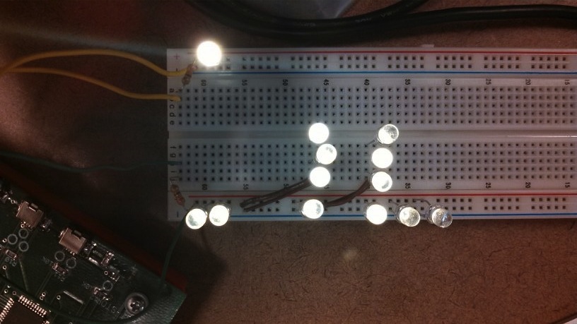
We started out with a very vague topic of "Art with Light and Shade." After a series of impossible ideas, we settled on hanging spheres of light. Though we originally wanted the spheres to be able to chase each other and move to areas of more or less light, we couldn't think of a good way to do that without derivative control, which would be very hard to implement with the Cricket.

The first thing we tested was using the sensor ports to power lights. With Robbie's help, we could light up and vary the power of the LED's on a breadboard. From there, I wrote a program for the static mode of the lamp as the works-like model. Next, we needed to come up with a program to run the motors. At first, we wrote the methods in the text language, but it produced a lot of inexplicable issues such as certain ports failing to turn on and ending the program in the middle. When Ashley transferred the method into the blocks language, the problems were solved.

Now we had a working program, but no physical device. We started by making the spheres and wiring the LEDs and light sensors into them. Then we had to think about the stand. We wanted a center-stem design with a domed top. At first, we just made the stand itself, which we designed in Solidworks and assembled on the same day. At this point, we were able to put everything on top of the stand and make sure that it would be stable. Then, we attached headers to the wires of the spheres and attached them to the Cricket, finished our winches with Delrin bushings, and had a working model. The only adjustment we had to make to our earlier program was to change the number of counts that the motors would go up and down, based on the length of the wires. Finally, we made a dome out of construction paper and the lamp was complete!

Final Testing:

Leading up to the exhibition next Wednesday, we did some final testing and recorded the results in this very positive and heartening table:
We will be presenting in the Engineering Lab, so we will be able to exhibit its features either by turning lights off and on, or by putting the lamp in a dark box.

Final Impressions and Improvements:

Overall, both Ashley and I were extremely pleased with our final product! A lot of things that seemed like they would be major issues, such as making a balanced stand and being able to winch the spheres up and down, turned out to be very doable. Although the lamp is far from our original vision of light spheres that could react to one another and move to areas of higher or lower light, it is really cool that it is able to react to ambient light in two different ways. It is also beautiful.

If we were to do this again, I think it would be helpful to plan all the components more concurrently, instead of, for example, finishing the LED control before we knew that it was even feasible to wire them inside of the spheres, and finishing the spheres before we had any idea what form the stand or dome would take. On the other hand, our linear approach ensured that all the parts converged at the end in a working manner, and subsequent parts were able to account for the quirks of earlier parts (for example, we could build the winches specifically for the spheres to hang on their wires alone, instead of strings and wires as we had originally thought it would be).

In the realm of improvements, if the spheres were heavier, they would do better at hanging down straight, and would not swing as much. If we added weight we would also have to come up with a better, more durable way to connect the wire and light sensor to the spheres. We would also have liked to adjust the stand so that the switch could have threaded down through the stem and come out near the base. Also, the dome could have been constructed better if we had glued one end of the paper strips at a time, making the dome more symmetrical and keeping the sides from bowing out. It would also be nice if we could come up with another dome material that might be more soundproof than paper, to make the sound of the motors less noticeable. Also, it would be worth looking into the reason why the lights blink briefly whenever a motor reverses direction, which we assumed was an internal Cricket quirk which might be hard to overcome.


Demo videos:


Photos of the completed product (and . . . others):


Acknowledgements:
Ashley Thomas was an awesome partner!
Amy Banzaert was ever helpful!
Robbie Berg knows a lot about Crickets!
Lyn Turbak asked a lot of questions!
Dania Wright is a dome genius!
Cassie Hoef thinks creatively about fire mitigation!

Saturday, April 27, 2013

More Progress on the Looks-like model

Today Ashley and I made a lot of progress on the aesthetics of the project. First, we completed the spheres, connected them to the wires they will hang from, added a light sensor to each, and sealed them shut.
They can now hang from their conveniently complementarily-colored wires!

The next thing we needed to tackle was the stand. We decided that it would not be too hard to make a wooden lamp stand using the laser cutter. After a few sketches, we created four Solidworks parts to create the stand.

Drawing of the base

Drawing of the platform

Drawing of the braces inside the stem

Drawing of the sides of the stem

Essie came in to help us print and we tested a set of notches in the wood we wanted to use before printing out the stand. After some troubles with positioning and issues with the laser not cutting all the way through, we had all the parts and our stand assembled very snugly!

Now, we will need to come up with a Lego platform for the cricket to rest above the three motors aligned above the three holes, and create a dome over the top to complete the look.

Looks-Like Model

After completing our program and adding a second "mode" in which the motors winch the lights up and down with a speed proportional to the light sensed, we focused on the physical design of the project. We had originally planned to house the lights inside of cardboard spheres, but these were not available. Instead, we created papier mache spheres formed around ping-pong balls.

These were cut in half and the insides were reinforced with glue at the suggestion of my roommate Cassie.

I made one extra as a test, and we poked LEDs into it and twisted wires to create a rough model.


We were a little scared at first to solder over the paper, but we got the go-ahead and created this much more sturdy version, complete with purple paint as well! 


We presented this as part of our looks-like model to the class.

The other part of our model was the winch and cricket assembly that will hold the hanging spheres. Our model is still crude because we have not decided on how we will raise these up, on some sort of stand, to have the spheres hang. For the moment we had them hang down from the edge of the table, though we want a "lamp" with a single stem so that it is more attractive and portable. 

Saturday, April 20, 2013

Works-Like Model: Lights

On Tuesday, I tested how many LEDs we could light up with the cricket. At first, I found that it could light up up to 20 LEDs while still being pretty bright:


But then I ran into a problem. The on8 and on7 methods that Robbie wrote for us only work for one port at once, so we couldn't have port 7 and 8 on at the same time. To work around this, I made a block program that turns each port on for 2 ms at a time, switching back and forth. This means that they can both be on at the same time, but they will only be half as bright.
With both ports on the single LED connected to the yellow wires (port 7) is pretty bright:
 Here the green wires connect to port 8 and the yellow to port 7, so the bottom seven lights connect to port 8 and the top single light is port 7
But when only port 7 is running, it is REALLY bright:

I decided that 12 LED's is a good number to be bright while still having many lights in each group. On Wednesday, I asked Robbie about the ports not turning on at once, and he produced a magical solution (I say magical because changing the last '2' to a '4' in all the methods means very little to me).
Turns voltage high and low for ports 6, 7,  and 8
Excellently, we can now have multiple groups of light at full power at the same time.
I also wired the LED's into three groups of 12, as we want.

Next, I needed to have a way to change the brightness of the LED's. This can be done by having them only be on for a certain fraction of the time, cycling too quickly for the eye to see. I wanted an easy way to set the lights to brighter and dimmer levels, and I decided on levels 0-10, where the number indicates how many milliseconds out of ten it will be illuminated. I created blocks for each port that will go through one 10ms cycle of light and dark:
In the process, I learned very valuable things from Robbie about the way the Logo language works, for example the only mutable variables are the global ones, (which seem to be capped at 14 variables, problematically), and :num is only a number, not a variable within the method, so it cannot be set to another value. 

But I wanted all three lights to be on at once, at different levels. With this system, because it uses long waits, only one light can be cycling at once. Therefore, I made another block that will do the same thing, but with all three lights at once, by waiting 1ms ten times, and turning each group on or off at the appropriate moment. I ran into a few fencepost errors with levels 0 and 10 and was sad at the lack of >= (and comments), but came to a final version that worked:
Now, all three groups can be at at different levels.

Now the lights needed to be interactive. I connected a light sensor to each of ports 1, 2, and 3, so that each group of lights can have a corresponding sensor. 
I wrote a program that will proportionally control each group of lights, increasing the power to each group when the light to its sensor decreases. The lights will be completely off at an arbitrary sensor value "midlight," here, 300, or slightly dimmer than the ambient light in the room. 
Now, the lights can be brightened and dimmed by covering or shining light on the three sensors:


But it seems silly to have an arbitrary value involved. 
Now, the light at which the LED's will not turn on is set by two things. "Avglight" gives the average light the sensors are seeing when the program is started, i.e. the ambient light in the room. We want the lights to turn on to a certain level at the ambient light. This is taken care of by a new variable "offset" which is the desired light power at "avglight" times the gain. Finally, "midlight," the light at which the LEDs do not turn on, is avglight-offset. This works by making sure that the "error" at the ambient light level (aka "offset") sets the light to the level specified in "offset." Here that level is 2, so the lights will go to level 2 when the sensors are reading the ambient light level as measured when the device was turned on. So, whether the device is turned on in a bright or dim room, it will adjust its range to be appropriate to the surrounding light. 

Tuesday, April 16, 2013

Component Testing

On Friday, we tested the lights and built a basic winch system for our hanging lights.

Lights

Robbie showed us how to transform the sensor ports into outputs using the following code:
Using the on8 and off8 commands, etc. we can turn the current in ports 6, 7, and 8 on and off. To adjust brightness, we make the lights flicker on and off so quickly that it is unnoticeable. For example, this program makes the lights only have current for half the time, making them half as bright. 
On Tuesday, I went into the lab to test the number of LEDs we will be able to use. We wanted about 20 in each sphere, so I tried out powering 20 at once:
They were still satisfactorily bright, not nearly as bright as a single one would be, but more lights, rather than brighter lights, would be more appealing with our sphere idea. But, I wanted to compare the many lights to the brightness of a single light, so I connected one light to the next port. 
Here I ran into a problem. Turning on power to one port shuts off power to the other ports, so a program reading "on8 on7" would only turn on port 7. As far as I can tell from messing with the underlying code, they can't be turned on simultaneously, though I will have to ask Robbie about this on Wednesday. To solve this, I wrote a program that switches power between the two ports every 2 ms. However, this has the same effect as the dimming program from earlier. The ports can't be at full brightness at the same time, since power is switching back and forth. 
In this situation, the 20 lights are probably not bright enough:
From here, I experimented with smaller numbers of lights to see how many would be able to still be bright enough with only half-power.
It seems like 12 is a good number for each group of lights, since they can still be quite bright while sharing power with another group. 

Winch

We built a simple winch out of Legos with an NXT motor which models what we will use to hang the lights. We did not include any gears because the motor's speed can be controlled through programming. We had some trouble with where the fixed end of the string/wire (the end that will be plugged into the Cricket) should go, but we decided it should trail off parallel to the axle so that spinning the axle will not pull on the fixed end.

Plans for Moving Forward

This Wednesday, I will try to make a works-like model, probably on a breadboard, that integrates feedback and control from light and touch sensors. Since Ashley will probably not be there, this might be a hard goal to achieve, but hopefully the model will be satisfactory. Depending on whether we have hollow cardboard spheres for the LEDs, I may be able to make one or more light spheres to test with the winch. I am afraid that they will be too light to hang nicely from the string/wire, since the wire could be stiff.

Thursday, April 11, 2013

Final Project: Brainstorming and Research

The goal of Ashley's and my project is "Art with Light and Shadow." On Friday, we made an attempt to narrow down that goal to an actual project description.

We started out with the idea of a panel with LED's behind it, which would sense light falling on it and respond by lighting up in return. We came up with a lot of cool ways that the lights could respond to sensor input (for example, if the average light dropped suddenly, such as when the lights in a room were turned off, the lights could brighten momentarily, or moving your hand across the panel would leave a trail of dimness behind due to the shadow). However, when we asked about the feasibility of this project, it turned out that it would be impossible with the control mechanism that we have available (the Cricket). This issue became a theme in the brainstorming process that we went through for the rest of the class period.

Going off of the theme of "art with light and shadow," we brainstormed a series of ideas from "light tic-tac-toe" to "morphing light cube." We did a lot of google image searches to look for inspiration. We eventually narrowed our ideas down to four that seemed most workable.

1. Light Boxes
This idea involves a bright constant light (or lights) inside of boxes made of thin Delrin, nested together. The inner boxes would have designs cut into them, so that the light coming from within would cast shaped shadows on the outer box. These boxes would be able to rotate within each other, for a constantly changing shadow effect. The movements would be controlled by light sensors on each face of the box, so that the box could respond to being moved around, or having one or more faces covered up or lit.

2. Light Fountain
The light fountain would be similar to the original panel idea, but the sensors (a maximum of eight) would be lined up at the bottom of the panel, and when the sensors were activated, either by light or by shade, a "fountain" of light would appear on the panel from long series of LEDs behind it. This improves on the original idea by having only a few sections of LEDs to control, and each section would operate as a unit. The different sections could be different colors, for a gradient effect.

3. Independently moving lights

Another idea similar to the first, but there would only be ~3 lights behind the panel, each attached to a horizontal and vertical string attached to tracks around the edges, so that each light could move independently in any direction. There would be a few sensors as well behind the panel, so that the lights could move toward the darkest section of the panel or rudimentarily interact with each other.

4. Hanging lights

This idea involved several (~3) small spheres encrusted with LEDs (like tiny disco balls) that would hang from the ceiling on a string attached to a motorized winch at the top, so that they could be moved up and down. Each sphere would have a light sensor, so that it would be able to light up in response to darkness (for example, cupping the light in your hands would cause it to be come brighter). We also wanted them to have touch sensors, either in the winch, so they could respond to a tug on the string, or on the sphere itself. These touch sensors would change the sphere between being attracted to and repelled from light, so that the spheres would be able to interact with each other, either chasing or fleeing one another.

We put these four top ideas into a Pugh chart. Our criteria were ease of assembly, ease of programming, time required, interactivity (very important to us!), prettiness aka aesthetics, suitability (does it meet the project requirements?) and feasibility (our nemesis).

The Pugh chart

We quickly discarded "Light Fountain" because we couldn't come up with a way to incorporate a mechanism into the design. "Hanging Lights" and "Light Boxes" came out on top, and we decided on hanging lights because they seemed more fun and interactive.

Hence, we started to refine the hanging light idea. We initially thought they could hang from the ceiling, but then decided it would be even better if they were on a stand, making the assembly like a desk lamp. We then asked again about the feasibility of the design. It turned out that it is nearly impossible to use the Cricket to power both motors and lights, especially bright lights, at the same time. Only the A, B, and C ports generally produce "variable" current, though the sensor ports could be used to produce a small amount of current, and the USB ports can only be used with the bulky single LED boxes we used on the first day of programming cars. We will be testing using sensor ports to power lights on Friday.
Improved sketch of hanging lights

Since the hanging lights idea was seeming less and less likely, we switched our attention to Light Boxes. Brainstorming on Thursday, we came up with the idea of the box being a puzzle, so that the two inner boxes would create words, or a coherent picture, when perfectly aligned as a result of the external lighting conditions. We also expanded this idea to have a pyramid instead of a box that would open up when the inner parts aligned, making it a true puzzle box for storing secret engineering secrets.
puzzle box sketch

On Friday, we will test the LEDs with the sensor ports, and if this fails, we will start developing our light box idea and see how much light will shine through sheets of thin Delrin, or if we need a different material, as well as getting experience with the motors and mechanisms we will be using.


Monday, April 8, 2013

Heating and Cooling a Resistor: Part 2

On Friday we continued our exploration of the resistor heating.

Deliverable 4: Proportional Control

Simulated proportional control
Proportional control

Proportional gain = 15, simulation in red, actual results in blue


  • If the gain is too low, the temperature will never reach the target because there will be a point where the power given to the resistor (error*gain) is equal to the amount of power being lost through cooling, causing the temperature, and the power level, to become constant, but the system will not reach the target. 
  • If the gain is high, the temperature of the resistor can overshoot the target and oscillate until it stabilizes. 
  • The ideal gain seems to be between 5 and 15 W/K, since the final temperature can get up to 304.8 without overshooting and oscillating first. 

Deliverable 5: Proportional and Integral Control


Simulated PI Control
PI Control with plot of desired (not actual) power
Simulated (pink) and actual (red) use of  proportional gain of 5 and integral gain of 1
After writing our script for PI control, we had a long process of optimizing the gain. At first, we set the proportional gain to 5 and the integral gain to 1. We attributed the dip in the graph to a gust of wind or similar. We then tried doubling the proportional gain to 10.
Simulated (pink) and actual (red) use of  proportional gain of 10 and integral gain of 1
Strangely, the system took much longer to heat up, even though the gain was larger. We added power to the graph to see if we could see what the problem was. At first, we were graphing the percent power output, by setting values over 100 to equal 100 and those under 0 to equal 0. However, we just got a straight line at 100. At first, we thought it was an error in the way we were graphing, but we soon realized that the batteries might be failing, causing the resistor to heat so slowly that the integral gain was huge and the power was always over 100. To fix this, we changed our target temperature from 305 to the more attainable 280, and made our integral gain 100 times smaller.

Power (black), temperature (red) and target temperature (blue) for proportional gain 10 and integral gain .01
The peaks in the above graph are from blowing on the resistor. We decided our proportional gain was too big, since the power, even when we were not blowing on the resistor, was jumping up and down from 0 to 100 because the gain was too large to stabilize the power at a constant level that would maintain the target temperature. We then reduced the proportional gain to 5.

Power (black), temperature (red) and target temperature (blue) for proportional gain 5 and integral gain .01
Reducing the proportional gain allowed the resistor to stay at a more constant setting when it was not being blown on. However, the response was still pretty slow, as can be seen in the middle peak of the above graph. We decided that our batteries were simply not strong enough to have a quick response at T=280, since setting the power to 100 still produced a slow response. Therefore, we reduced the target again, to 260.
Power (black), temperature (red) and target temperature (blue) for proportional gain 5 and integral gain .01, target 260
When the target was set to an attainable temperature, we got good results even in fairly strong "wind." The desired power did not have to go above 200 because the system could respond more quickly to changes.